Friday, November 28, 2008

SIZING UP YOUR STREAM FOR HYDRO POWER

The huge variation in stream flows during a season make exact measurements difficult and un-necessary. We experience 500 to 1 in a typical season, and I have seen 5000 X more water than typical low flows. An existing dam, batter board wier or even a place in the stream where all the water is flowing through a fairly constant depth channel or puddle will do to make observations and measurements that are detailed below. I think a computerized data logging setup is ideal but over kill. It is also likely to go down stream in the first big storm. And if you are lucky enough to experience a 100 year event you'll not only lose your equipment and maybe your dam, but you will see first hand what your intake structure has to be built to withstand! And yes, that wooden flume is temporary / test. It will be upgraded to stone (for aesthetics) and concrete for strength and durability. Look at the live webcam on the intake
http://powershack.shacknet.nu:1026/


Why measure something that varies sooo much so exactly? Any experienced hydrologist or keen long time observer of a stream can tell you the 'design flow' to use for your micro hydro setup. A hydrologist or you could determine the watershed area by studying Google earth. The watershed area and the number and size of the lakes and reservoirs tells you a lot about your stream or river. Our watershed is only 1.5 square miles and contains only one 2 acre pond. Our rainfall data shows about 50 inches / year, another figure to add into your considerations. Then you should try to determine (by a few measurements throughout a year) 'Q95' , the Quantity of water flow that is exceeded 95% of the time. So only 5% of the time there is less water and you won't be able to run your system effectively and leave enough water for the fish.


Another useful figure to estimate is 'Q50' , the quantity of water exceeded half the time throughout a year. This is the upper limit on your design flow and you will tend to spend more on bigger pipe and turbine, run for only half the year (on average) but produce the most KWhrs. This design flow should only be considered if you are grid connected and selling back. I selected Q75 (1800 Gal/min in our case) for our design flow because we run autonomous (totally off the grid) for 9 months when we have plenty of water to make about 20Kw 24/7, all of which we try to use up in 2 1/2 households.

We switch back to the local utility for a few months in the late summer when we don't use much electricity anyway, and don't have enough water to keep Q95 (150 Gal/min) flowing. My ultimate goal is to work out an arrangement with the utility company to become grid connected. Then we could 'store' the winter generated excess power in the grid and withdraw this 'stored' energy during late summer. Ideally the Utility would allow us to 'net meter' like they allow for wind, solar, and bio generated electricity. Net metering does not require any special equipment or meters, the energy flows both ways, and your existing meter runs forward and backward to keep track. But alas, the Utility in their infinite wisdom, excludes Micro Hydro from net metering. So we should all lobby to get net metering for all renewable energy. Even a cap, of say 25 KW, would be acceptable. Beyond 25 KW you could probably justify the expenses of special meters and switch gear. Now I'm Getting off topic.

Happy Hydro!
Rob

Make webcams work over long distance ethernet.


Find the WEB CAM in the picture ...
Here I used the 6X6 plastic box on its back. The camera and the clear cylindrical food storage container is mounted on the box cover, and the Home Plug Ethernet Switch and camera power supply are all in the box. Just a pair of #18 wires powers the whole thing and carries the ethernet video signal back to the house and the internet. The camera works even on the coldest days (-5° F so far) because of the small amount of heat generated by the power supplies. Cost: IP camera-$80, One Home Plug-$50, Carlon 6X6 box and clear food container- $20. The other end at the house costs about $70 plus 1000 feet of Cat 5 wire. The most expensive part is trenching and plastic conduit. But if you do it by hand you won't need that workout at the gym for a long time :)


POWER YOUR WEBCAMS AND SEND STREAMING VIDEO THOUSANDS OF FEET OVER ZIPCORD!

Yea, these little webcams, IP cams or internet cameras, are cheap (<$100). What costs is hooking them up using fiber optics over long distances. Wireless does not work over more than a few hundred feet and line of sight. You still have to run 120VAC to them, so why not send the streaming video over the same power wires? I've got 4 running now, the one in the power house is 1400' away! That one is just aimed at the circuit monitor meters.


These web-cams have web-servers built-in. That means they act just like a computer on the internet and you don't need a computer running all the time. The camera all by itself can send its imagery to anyone that logs on and requests it. You can set up the camera with user names and passwords, and you can access the camera from anywhere on the internet. I did have to learn a lot about IP addresses, port forwarding and such to get the first one to work. It took me a while to figure it all out, and then I went out and bought a different brand of camera and it was like I had to re learn everything all over again because it was all slightly different and it did not help that the manual was in Chinese or a very rough translation there-of.


Try http://www.powershack.shacknet.nu:1027/ Use Guest login. You'll be looking at the 2 Square D Power Monitors set to read out Amps @ 500V and 3 mirrors, the lower left mirror shows the control valve position, vertical black line is wide open, 45° is shut down to minimum power. The wide angle mirror gives a view of the inside of the power house. Also try the intake cam at http://powershack.shacknet.nu:1026/ (during daylight hours- will have night lights soon.) The biggest challenge was how to get ethernet to work at 1400 feet distances and at the same time get power to the camera. Now I had already installed cat 5 wire all the way to the powerhouse, but when I tried to connect the camera in the power house to my computer 1400' away at home I got nothing, even though it worked fine when there was anything less than about 500' of cat 5. I solved that problem by buying a pair of Netgear 'HomePlugs' for about $100. These things are designed to plug into any 120VAC outlet and have 4 ethernet connectors. They are intended for extending your ethernet network in a home by using the existing 120VAC power wiring in a house. So you plug one in the wall in the living room, plug your computer in to it, plug another one in, say in the den at the other end of the house, and plug in the second computer or any ethernet device.


Now I could not use the power line going between the power house and my house because it is 500VAC. So I paralleled 2 pairs in the cat 5 wire, and with some fuses and filtering essentially plugged the Cat 5 into 120VAC at the house, and a HomePlug at each end. (see drawing above for details) At the powerhouse end I also connected the wall wart that powers the webcam to the 120VAC that also powered the HomePlug, and then just plug in the ethernet cable from webcam to HomePlug. With this setup you could run 16 guage zip cord thousands of feet , power the webcam at the far end and get video streams at up to 85 Mb/sec. back over plain old zip cord. Some models of HomePlug go up to 250Mb/sec. !


The only other option I came across in my research was to run fiber-optic, but that would have cost 10 times what this setup cost me. In the mean time I have added 3 more webcams ( and 3 more HomePlugs) all in parallel on the same doubled up pair of #22 cat 5 wires and I can't really see much degradation in speed or image quality. I have all my long distance wire underground in conduit. If you plan overhead wire you'll need to consider more fuses and surge suppressors in case of lightening strikes. Even my underground wire got enough of a surge during a recent thunder storm to blow a 1 Amp fuse, but no other damage.


Disclaimer: 120VAC is dangerous and should only be used with the proper wire in the proper conduits and with the correct fusing and ground fault protection. Only qualified persons should deal with electricity. The unqualified may be fried!


http://www.netgear.com/Products/PowerlineNetworking/PowerlineEthernetAdapters/XE104.aspx

These are the links to the NetGear hardware.

Tuesday, November 25, 2008

Dealing With High Water, Leaves, Sand, Gravel, Rocks & Ice

The most difficult part of a hydro project is building it to deal effectively with the extremes of nature. Of the various challenges nature provides the most difficult (in our situation and location) is extreme cold. When the temperature drops towards zero degrees F the water running over the rocks becomes super cooled ( below 32°F). It turns to slush and plugs up any trash rack in the way. Compare this summer low water scene looking down stream into the intake flume and trash rack to the high water and winter scenes.


The slush completely blocks the trash rack and any liquid water runs around the intake. This shot is looking up stream, note the big rock that guides the water directly into the flume. Since there is very little debris in the slushy water I removed both the primary and secondary self cleaning trash racks to keep things flowing. With no metal parts for ice to build up on and attach itself, I was able to keep it flowing down the 550' of 8 inch steel penstock, but only after adding some insulation to the penstock where it could not be buried. This year I added a small (1/2") buried plastic pipe that feeds 45°F water, in winter, from a spring a 1/2 mile away and 150 feet up. This warm water squirts out and upstream from the intake at 1.5 gal/min. We'll see if it helps keep things flowing. I need a dubious emoticon here. It sure can't hurt. I'll report back.


The insulation I used is only about a quarter inch of foam, ordinarily used to seal between a footing and the sill plate of a building. It comes in 50 ft X 8 inch rolls at building supply depots. To protect the foam I spiral wrapped it with high quality roofing underlayment, and coated that with rubberized roofing compound. To make the spiral wrapping process manageable I cut the 3 ft rolls in half. Start the wrapping at the bottom and overlap a couple of inches so it sheds water. Note the power and control conduits are strapped to the penstock with stainless straps and are included in the insulation.


This is a picture of the first year freeze-up being thawed out. The ice covered dam is visible in the distance. This freeze-up probably would not have happened if the water had continued to flow into the flume, but I suspect that the trash rack gradually reduced the water flow to a standstill causing everything to freeze.


Here is a picture looking down the 200 foot waterfall in winter. There is actually water flowing under there! Note the as yet un-insulated penstock upper left going slightly down hill.


This shot shows the (temporary/test) intake box that has baffles and screens to separate the water from gravel, leaves etc. The flume is not yet installed. The gravel dump valve oulet is directly under the '24'. The penstock is right under the '7' and there is an 8 inch butterfly valve stem visible just above the '2'. See the drawing posted for more detail. This intake structure, being successful, will be made more permanent with concrete before the wood disintegrates. I hope it will last a few more seasons as is.
Try this link to a live webcam monitoring the intake, http://powershack.shacknet.nu:1026/

Click on Guest visit. Will have night lighting soon.

Saturday, September 20, 2008

Pump as Turbine (PAT)


This is the latest addition to the powerhouse. This split case PAT, 5X6X9 driving a 30HP 3 phase motor as generator will be able to take advantage of the much higher winter flows of the stream. The pump/turbine has been mounted at a 45° angle to eliminate 2 right angle bends in the powerhouse plumbing and there is enough room to accommodate a large flywheel on the generator shaft to enhance mechanical momentum. This will improve voltage regulation and large motor starting capability.

I have a number of Distributed Load Controllers on 1.5kW space heaters in the winter months when there is plenty of water. Then the turbine control valve is wide open all the time and DLC's will have the heaters going full blast until a refrigerator or well pump comes on. Then the DLC's will proportionally reduce the power to the heating loads to keep the voltage constant and allow the motor loads to start up. The 3KW dump load and DLC in the power house penstock is set to a slightly (5V)higher voltage to react to over-voltage situations that might arise if the valve is wide open and loading suddenly decreases. That dump load will absorb the extra power and give the (slow) motorized butterfly valve a chance to close and reduce the power. It is when we are lightly loaded in the spring and fall that I think the flywheel idea will help to regulate the voltage better. I have also just put a few DLC controlled electric heaters outside! Such a waste, but it keeps everything stable.

We are still in drought conditions and waiting for more rain before I can run at full power with the valve wide open. (Our drainage area is only 1.5 square miles) I'm thinking about adding a small efficient pelton to use around 1 gal/sec @ 210' of head so we can keep running through the summer months. Of course none of this would be necessary if we were grid connected on net metering. We are just getting started on the paperwork to get grid connected. To me it seems a bit daunting because I don't like to do paperwork or deal with bureaucrats.

Saturday, August 23, 2008

Smart Grid of the Future

• Eventually, the smart grid will let rates fluctuate even more dynamically, depending on conditions. This already happens in wholesale electricity markets, in which power suppliers buy energy from power producers. Now that would extend to the retail level - our homes. The price of electricity would dip when demand is softest, typically at night or on mild days, and rise in periods of strain. This would require appliances to be designed to interact with the smarter electric grid in order to adjust themselves.

• The Department of Energy's Pacific Northwest National Laboratory has already built and tested controllers that can make these adjustments happen. And over the next decade, it is expected that homes will have appliance controls with a sliding scale. At one end people could choose something like "maximize my ease and comfort." At the other, "save me the maximum amount of money." The highest-conservation settings might lead dishwashers to start only when electricity prices are at their lowest, or when hydro/wind power has kicked in.

• New electric meters coming...


Wednesday, June 25, 2008

Grid Connected Or Autonomous?


We have been up and running autonomously (off the grid) with 12KW capability. On average our little mini grid only draws 2 to 3KW so all the rest gets wasted in dump loads or as water over the dam. (It does make a pretty waterfall!) If we generated this electricity with solar panels or wind we would qualify for 'net metering' which requires very little in the way of special switching and essentially allows you to store energy in the grid, running your meter backward. When your generated energy drops due to darkness, no wind, or in our case no water in August & September, you would draw energy from the grid running your meter in the normal direction. In our case we would be sending the grid much more energy during the ten months that we have ample water than we would use in the couple of dry months. We would gain the frequency and voltage stability of the grid and we could do away with all the voltage / frequency controls, governors, dump loads and associated controllers, simplifying the system and maintenance. We have a transfer switch which will connect us to utility power if our hydro drops out, and back to hydro when that comes back up. But we can never connect both power sources together legally even though technically this is the best for all parties! The utility / grid would get the excess energy we generate in a year, and we would use the grid to store the energy we need for a couple of dry months and simplify controls while increasing stability. There is no safety issue using an induction generator directly connected to the grid (through a standard meter and disconnect) because this type of generator will stop producing current when it senses no excitation voltage from the grid. Thus if the grid goes down so will the induction generator. This may be disappointing if you were hoping to get through the next grid blackout with your own power, but then you could disconnect from the grid and switch in some excitation capacitors to run autonomously if you can muster more than a few thousand watts on your own.

Utility Company Meters

Utility company meters come in many flavors. I discovered that (shortly after getting our micro hydro running) that our meter measures 'absolute' power. This means that the meter does not care weather the power flows them to us or us to them. It just keeps increasing the meter reading (and our bill) even when we send power to the utility! This tactic is what keeps me from connecting to the grid and sending them (free) power, and paying for the privilege. We used to have an older spinning disk meter. This type would decrement the meter reading when power flowed to the utility and increment the reading when we drew power. This is the 'net metering' setup that would benefit all parties. The best they could do with those meters is put a ratchet on the spinning disk so it could only spin forward, incrementing the meter reading when drawing power, but it would just stand still when you sent power their way.

Sunday, June 1, 2008

Butterfly valve voltage controller

Here are two views of the 4 inch butterfly valve and modified (a little) car window operator that modulates the valve to keep the voltage steady as power demand varies.

Frustration overcame when I tried to upload PDF files to my blog, so here is a link to the PDF diagram for the valve controller. The butterfly valve is driven by a car electric window operator because of its high torque and harsh environment operating capability. The controller was built to operate 2 valves and has battery backup for manual control, when all else fails.


http://www.scribd.com/doc/3198857/Valve-Voltage-Frequency-Control-Circuit


Download http://www.scribd.com/doc/3198677/3-phase-motor-as-1-phase-generator-diagram.pdf

Saturday, May 31, 2008

How I got started, overview.


Three years ago I started designing this system on the waterfall by our house that I had been eying for energy for 35 years. I partnered with the owner of the waterfall which is just off the edge of our land. We shared expenses, I did all the engineering, the partner contributed access rights, labor and graphic design, I have a dump truck, back-hoe, bulldozer and a big, well equipped shop. We share the power output of the project.

Since so much of the cost of the project was in the penstock, powerhouse and (wiring) infrastructure, I decided to try a Pump As Turbine (PAT) before spending a lot of money on a commercial turbine/generator. As it turned out my initial calculations for a 4 nozzle Pelton showed that it could deliver 14KW. I figured out that a 3X4X9 end-suction centrifugal pump with a 30HP 3 phase motor and capacitor bank could deliver close to that but for 10% of the cost of a new Pelton. I also have 12 feet of suction head below my powerhouse floor that I would be giving up if I used a Pelton.

Centrifugal end suction pumps are readily available (on Ebay) and reasonably priced. I got mine for $500 with the motor, and paid another $300 for freight from somewhere in the middle of the country. I had read somewhere that PAT's were difficult to control, but I decided to try a butterfly valve control anyway. It works well with a simple servo that looks at the line voltage and runs a 12V high torque servo motor on the valve. (in fact an automotive electric window operator mechanism) This setup gives rudimentary and somewhat slow voltage regulation.

For fast response to load changes I developed PIC16F818 based Distributed Load Controller(s) that are on all the water heaters (and space heaters in the winter). These controllers simply look at the line Voltage and Frequency, and if V/F drops by a presettable amount (3%) the controller reduces the power to the load (water heater) thus raising the voltage and allows the butterfly valve time  to open up some to supply the needed power. Conversely, if a load ( like a refrigerator) shuts off the voltage will tend to rise and the Distributed Load Controller(s) will boost the power to the ( water/space ) heaters thereby lowering the voltage. I have found that at nominal line voltage we run at 60 HZ +/- 1Hz with the load ranging from 5KW to 10KW. I am currently working on computerizing my instrumentation so that I can log and plot the various parameters. Then I'll have a much better idea of overall system performance and stability.

I have also had an interesting time designing an intake structure to accommodate flow rates that vary 1000:1 with 500lb boulders, rocks, gravel, sand, leaves, logs, sticks, and worst of all frizzel ice in winter. I hope to have time soon to add some details to my blog.

Tuesday, March 4, 2008

Tuesday, February 5, 2008

Thoughts about penstock sizing and PVC.

Sizing penstock pipe is not a very exacting science. The low to high flow can vary by a factor of thousands. In an average season we get 1000 to 1 winter to summer. So picking the 'design' flow I figured out how much water we can draw during the 10 wettest months and still have a reasonable waterfall too. I figured that a couple of months in the summer we would have to reduce water use or shut down. So if you make your pipe big you'll spend more money on pipe but you'll generate more power during winter. If you make the pipe smaller you will not be able to capture additional energy during the winter but you'll have enough for your needs all year long and save money on the pipe purchase.
So in short, look at the pipe prices and spend as much as you can on this.
Up to 50% of your total budget is reasonable.
If you are looking to sell power back to the grid then spend more on bigger pipe.
If you are just looking to cover your own energy needs go for smaller pipe.
I highly recommend steel pipe for penstock, over plastic for heads over 100 feet. Even though 6" schedule 40 PVC pipe can handle 160 PSI, I had a T burst as I was making a minor adjustment to a butterfly valve. The static pressure in the powerhouse was 95 PSI.

Look at the picture.


For powerhouse plumbing I still use plastic because it is so much more available (in smaller sizes 2,4,6 inches at Lowes) and cheaper and easier to glue together. Six inch PVC is not as readily available in schedule 80 as schedule 40. So I wrapped the schedule 40 PVC (after assembly and glue up) with fiberglass tape and coated it with resin to make it as strong (or stronger) as schedule 80 PVC.


This is the place we got our steel pipe. Shipping (Ohio to NY) was $800.

Crestwood Tubulars, Inc.
P.O. Box 6950
St. Louis, MO 63123
800-238-7473
314-842-8604
(Fax) 314-842-9064


New & Used Steel Pipe Specials

10000’ 3.500” x .254” SRL/LRL Used Bare $1.59/ft Ohio
35000’ 4.500” x .205” LRL/DRL #2 Used $2.30/ft Ohio
16000’ 4.500” x .205” LRL/DRL New Surplus $3.38/ft Ohio
9000’ 4.500” x .224” LRL/DRL New Surplus $3.65/ft Ohio
5000’ 4.500” x .237” DRL #1 Used Cleaned $2.95/ft Okla
4000’ 4.500” x .237” DRL #1 Used XTRU $2.95/ft Ohio
2300’ 5.500” x .244” SRL Used, Bare $3.95/ft Ohio
2200’ 6.625” x .188” SRL New Bare $4.50/ft Ohio
4000’ 6.625” x .250” SRL/DRL #1 Used, Bare $5.95/ft IL
26000’ 6.625” x .250” DRL #1 Used, Bare/FBE $5.75/ft OK
2000’ 6.625” x .344” DRL #1 Used $6.50/ft Okla
2000’ 7.000” x .231/.272” SRL/LRL #2 Used,Bare $4.35/ft Ohio
50000’ 8.625” x .219” DRL Good Used, Bare $5.75/ft Okla
3400’ 8.625” x .219” D/TRL New Surplus FBE $7.85/ft Ohio
7500’ 8.625” x .264” SRL/LRL #2 Used, Bare $4.95/ft Ohio
25000’ 8.625” x .300” 50’ R/L, #1 Used, Good Yield $7.25/ft TX
4000’ 8.625” x .322” Good Used, Bare, DRL $7.75/ft TX
4500’ 10.750” x .250” D/TRL New Surplus FBE $9.95/ft Ohio
1200’ 10.750” x .365” DRL Used Bare $12.95/ft Okla
27000’ 12.750” x .250” DRL #1 Used FBE OD $11.25/ft TX
1800’ 12.750” x .250” D/TRL New Surplus FBE $13.90/ft Ohio
5000’ 14” OD x .312”DRL #2 Used, Bare $14.35/ft Ohio
2000’ 14” OD x .375” #1 Used Srl/DRL $19.50/ft TXs
1000’ 16” OD x .250” DRL New A252-3 $21.00/ft Ohio
2000’ 16” OD x .250” DRL #2 Used $16.00/ft Okla
3500’ 16” OD x .312” DRL New Surplus FBE $20.00/ft Ohio
1700’ 16” OD x .500” DRL Used, Cleaned $24.00/ft Ohio
1000’ 18” OD x .250” DRL New A252-3 $23.50/ft Ohio
400’ 18” OD x .375” SRL/DRL #1 Used $26.50/ft Illinois
2000’ 22” OD x .250” DRL #1 Used Cleaned $22.00/ft Illinois
1000’ 24” OD x .375” DRL New Surplus, Pritec $29.90/ft Ohio
2000’ 30” OD x .312” 20’0” #1 Used Cleaned $45.00/ft Ohio
100’ 36” OD x .330” #1 Used, DRL, Cleaned $59.90/ft Okla.
240’ 48” OD x .375” 40’ New A252 Spiral $88.00/ft Ohio
Prices are for truckload quantities. Please call us at 1-800-238-7473 for more details, processing costs and delivered prices. Many other sizes in stock and much more on the way! Please call for prices on all your pipe requirements.

Friday, January 18, 2008

Operator Manual Excerpt: Fine Tuning Micro Hydro


BMH Power Plant Engineers Operating Manual
August 2014
Robert J. Honders Sr. CE

Summary

A micro hydro turbine driving an induction generator is like a finely tuned instrument. It runs most efficiently when water flow and head pressure resonate mechanically with the turbine geometry and the rotational speed. The rotational speed generates a precise pitch of 60 cycles per second which in turn is tuned to resonate (electrically) with the load and a bank of capacitors to keep currents oscillating through the copper windings of the generator and create magnetic fields in synchrony which in turn produce the current that we can use to light up our lives.

Since there are significant energy flows to be controlled and contained, it is important to understand how to control the energy smoothly, avoiding sudden surges or stepwise impacts in both the electrical as well as the hydraulic circuits.  The operator, typically an engineer or highly trained technician, must understand, and be able to predict the result of turning On or Off any circuit breaker, switch or valve before actually touching a breaker, valve or controlling device. (In many localities grid-connected power plants are required to be operated under the supervision of an engineer.) Always check the readouts first to find out what loads are being powered when making any changes, and try to anticipate the result of the adjustment and the effects on the connected load. This manual will explain each switch, breaker, valve and controller and the function each serves.

This manual will give the procedures for startup of the plant, planned shutdown, unplanned shutdown and subsequent startup procedure. Monitoring and metering will also be explained. It may be useful for the more experienced operator to refer to the diagrams for further insight to the operation of this plant.

Conventions and Definitions as they apply to the Buttermilk Micro Hydro plant:
(Starting from the top.)

Storm Water Diversion: currently a pair of logs placed at an angle ~12 feet upstream from the water intake. Their function is to protect the down stream intake structures during extreme weather events. (Maintenance or future enhancement / automation project.)

Water flow measuring weir: located immediately upstream from the water intake. Functions to get an approximate measure of total water flow reaching the intake. (Maintenance or future enhancement / automation project.)

Slide gate: at the entry to the flume, function is to shut off water at the water intake during severe weather events or flume repairs.

Water intake: the 8” x 48” rectangular opening in the upstream end of the flume.

Warm water feed: the warm Honderosa spring water fed via (blue) underground pipe that keeps the water intake from freezing closed during most subzero winter nights.

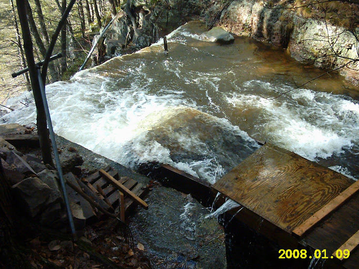
Flume: the structure that currently carries the water from the water intake to the gravel baffle (and screening) box. (Maintenance or future enhancement /automation project.)

Minimum flow bypass: the circular opening in the flume bottom that insures the escape of a minimum of 200 Gallons / minute to keep the waterfall hydrated. (Maintenance or future enhancement / automation project.)

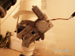
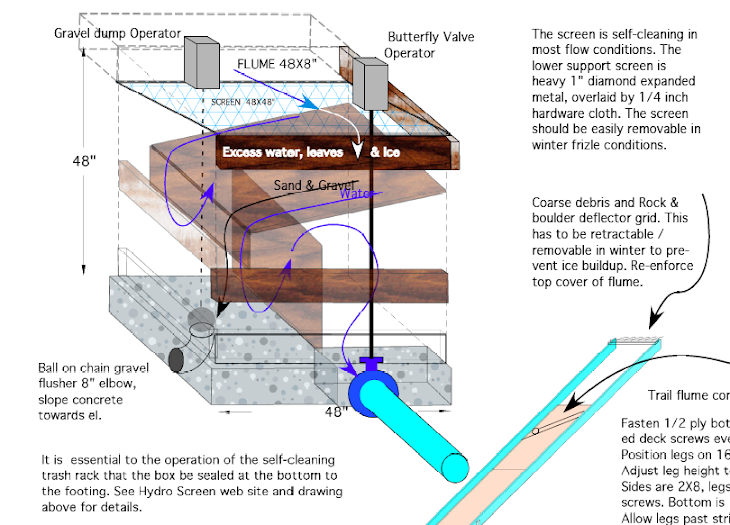
Gravel baffle box: the 4’ x 4’ x 5’ high (wood) box (Maintenance and / or future enhancement / automation project.) with the integral second gravel chamber and attached first gravel chamber, ball and chain flush valves, moving screen, screen drive mechanism, head valve, head valve drive / operator, and attached to the flume upstream. 

Gravel Chambers: the first gravel chamber removes most negative buoyancy material that did not fall out of the minimum flow bypass. The second gravel chamber mostly collects fine sand and mud. (Maintenance or future enhancement / automation project.)

Moving screen: the HDPE conveyor belt screen that functions to keep floating or neutral debris from going down the penstock and clogging the turbines. The screen duty cycle can be adjusted so it does not clog itself with heavy debris loads or frazzle ice formation. (Maintenance and / or future enhancement /automation project.)

Frazzle ice: the slushy watery ice that forms in the shallower upstream rapids as water is super-cooled during sub zero nights. The frazzle ice solidifies immediately when it meets any cold or metal surface and blocks water flow. Once ice covers the stream no further frazzle ice will form and the water will run unimpeded underneath the ice cover, more so if snow also covers the ice. Even water falling vertically will be covered with ice.

Head valve: the butterfly valve and operator (motor and drive circuitry) at the bottom outlet of the gravel baffle box where the penstock connects.

Penstock: the 8” insulated or buried steel pipe that keeps the water contained
as the pressure increases going down to the powerhouse.


In the Power House

Indicators:
Green LED: indicates normal, OK, valve open, valve opening, green condition.
Red LED: indicates fault, valve closed, valve closing, red condition.

Orange Neon: indicates no power or reverse power flow from grid to generator. The Orange will extinguish when generator is operating normally and producing power.

NO: Normally Open contacts / circuit
NC: Normally Closed contacts / circuit

Manual Controlling Devices
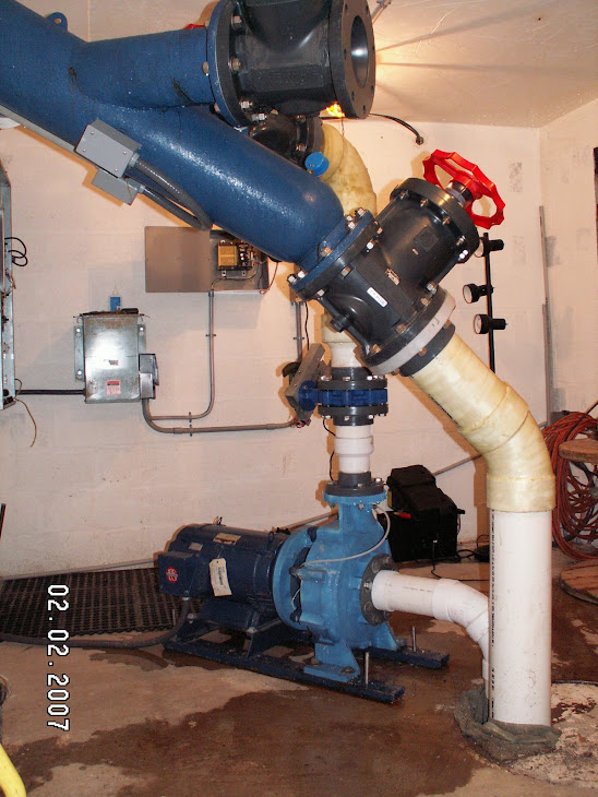
Valve1: The large PVC valve with red hand wheel that controls water flow to GEN1.
Valve2: The large PVC valve with red hand wheel that controls water flow to GEN2.
Valve3: The large PVC valve with red hand wheel in the middle that controls the dumping of water and debris into the discharge pit.

Rotating Machinery:
GEN1: Smaller 10kW turbine / generator
GEN2: Larger 15kW turbine / generator

Electro-mechanical Controlling Devices:
Rotork1: Valve and valve controller on GEN1 functions to automatically keep the speed of GEN1 constant when set to AUTO.
Rotork2: Valve and valve controller on GEN2 functions to automatically keep the speed of GEN2 constant when set to AUTO.

Electrical – Electronic controlling devices:
Main distribution panel
.
.
.
will add more, see comment balloons on Buttermilk manual 1.2.PDF


I. Start-up of water flow at intake

During warm weather months the flow of water to the turbine may be started (acquire ‘green’ condition) by following these steps.


The initial conditions are:

a. All power house valves closed, No water flow.
b. GEN(1 and 2) Rotork in manual / local mode and operated to CLOSED position.
c. Utility power present and fed through to homes, transfer switches in Normal mode, not Utility / Emergency.

1. Insure that there is at least enough flow in the stream to support turbine/GEN1 operation. This can be judged by observing the flow into the flume. Standing on the flume looking upstream, the water should cover ~80% of the width of the sloping bedrock stone weir, or within ~20% of the right side of the flume. (This measurement method should be refined when the temporary intake structures are made permanent by having a constant slope and marks ground or cemented into the trailing edge of the bedrock leading into the flume.)

2. Check that the moving screen (trash rack) is clear and operational. (see:Moving Screen Maintenance) Flush the 1st and 2nd sand and gravel settling chambers by pumping the ball valves (via stainless chains) up and down several times or until the water flows clean from the flush opening. (This procedure should be refined when the temporary intake structures are made permanent.)

The head valve can be operated from the powerhouse by a single push of the button on the Head Valve and Communications control box, observing the green LED for valve open and red LED for valve closed. An additional red/green LED lights only while the valve is moving to its newly commanded position, which takes ~100 seconds. Each push of the button reverses the operation of the head valve from open to close and vice versa with a 2 second delay.

Continuous operation of the trash rack can currently be implemented manually from a control box at the top of the falls in the old pump house. (Maintenance or future enhancement /automation project.)


II. Start-up of co-generation. 

The initial conditions are: all the above and:

1. The ORU utility grid is assumed to be always present when starting up. If ORU fails while BMH is running, BMH continues independently, disconnected from the grid automatically via the Beckwith 3410 intertie protection device.

Open Head Valve (press button once on Head Valve and Communication box), wait for valve to open as indicated by ONE green LED. (the ‘green’ condition)
After 15 minutes check that pressure is stable at 95 PSI. (It was previously insured that a good volume of water is available in stream above and no ice/sand/gravel is present in penstock water.
(See: “Winter Icing Conditions” for cautions.)

2. Utility grid power ON. Beckwith 5 minute timer expired and ‘Output 1’ RED LED is ON and GREEN LED is blinking.

3. Top four load side breakers ON. We are using grid power as indicated on the Net Grid meter lower right in Beckwith enclosure.

4. Bottom six Generator side breakers OFF. We are not making any power yet.

5. Check for nominal meter readings of Honders ~1-3kW, Buyske ~ 1-3kW, NET from Grid −3kW to −8kW on PM620 meter in lower right hand corner of Beckwith enclosure. (The signs will change once the PM620ʼs are directionally adjusted to conform to Utility practice.)

6. REV PWR RESET to OFF (down) (located under Beckwith 3410)

7. Open the GEN 1 or 2 (which ever one is being started) manual main (RED WHEEL) valve to 50%. A red line on the valve stem indicates 50%.

8. Open GEN 1 or 2 Rotork in MANUAL mode to get RPM ~2000 using manual mode with the lever and hand-wheel or local control with open / close switch. Observe open / close LEDs in Rotork housing, after alternating red/green both should be OFF indicating speed is within range.

8. Switch REV PWR RESET to ON (up) (located under Beckwith 3410)

9. GEN1or 2 breaker ON, never both.

10. C1 breaker ON for GEN1. C1 and C2 breaker ON for GEN2. (Do not run both GENs simultaneously.)
11. Switch Rotork valve to REMOTE (automatic enabled). The Rotork controller should now open the valve slowly to maximum power.

12. Observe pressure gauge reading, (~90 PSI GEN 1, ~80PSI GEN 2), holding steady, not dropping for lack of water at the top or too much power input to GEN2. If too much power revert to manual control, 5/8 open 80 psi.
Check that the Reverse Power Relay ORANGE light is OFF.
Check PM620 Grid Power, Summary kW3Ø 5 to15 depending on house loading.
Check that power factor, PF3Ø > .90 or as close to 1.000 as you can get by switching breaker C2 and/or C3. Closer to 1.00 is better. If PF3Ø is - (negative) then turn off C3 if you can get closer to +or- 1.00
Check that the pressure remains stable at ~90 PSI GEN 1, ~80PSI GEN2.
If it is raining/snowing be sure to set the trash screen to continuous mode to prevent clogging.

13. GEN1or2 set the Rotork valve controller to REMOTE (automatic enabled).

14. Set (Honders and Buyske) house meters to read kW3Ø.

15. Switch REV PWR RESET to ON (down) (This may change with further automation.)


III. Shut-down of water flow.

During warm weather months the flow of water to the generator may be stopped (‘red’ condition) by closing either the head valve, the manual valves, or the Rotorks in the powerhouse and following this sequence:

The initial conditions are:
a. Head Valve open, normal water flow. ‘Green’ condition.
b. GEN(1 or 2) operating, Rotork in automatic control mode.
c. Utility power present and BMH power fed back to grid and through to homes, transfer switches in Normal mode, never Utility / Emergency. (This can be assured by opening the main breaker, interrupting the O&R ‘Emergency’ source from the ASCO transfer switch at the house.)

Sequence to follow:
1. Set the GEN(1 or 2) Rotork to Manual.
2. Switch REV PWR RESET to OFF (up) (located under Beckwith 3410)
3. Set the Rotork to manual / local control mode.
4. While observing the Valve position indicator on the Rotork operate the valve to its fully closed position. All should be quiet now.
5. Turn off all (lower) Generator side breakers. Do not touch the upper 4 Load side breakers.
During cold weather months or anytime there is a danger that BMH may stop generating power it is best to switch REV PWR RESET to OFF (up) (this will change with further automation.)

During cold weather months the stream water flow must be kept from entering the penstock by:
1. Lowering the slide at the entry to the flume. (needs improvements with the rebuild)
2. Pull up 10” and hook both gravel flush ball valves.
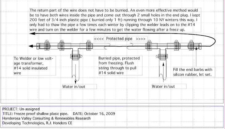
3. Check that warm water flows down penstock to keep it from freezing solid.
4. Turn off all (lower) Generator side breakers. Do not touch the upper 4 Load side breakers.

Winter Icing Conditions — CAUTION

Over the years I have made continual improvements to the ‘temporary’ intake structures to mitigate some of the problems with slush and ice in winter, leaves in the fall, sand gravel, rocks, logs and debris washed down every time it rains more than an inch or two overnight.

Most winter problems would be greatly reduced or eliminated if there was a deeper reservoir to draw water below the surface ice layer, but not so low as to suck up sand and gravel. ( An 8” high x 48” wide opening just above the low, upstream, end of the moving screen could be opened to take water in through the screen if the water level is raised just above this opening.) The first fall excursions to single digit temperatures will probably not cause slushy (frizzle ice) water. But after a day or two of sub-zero nights frizzle ice will start to dam up flowing water especially any place where there is the slightest restriction or shallow water flow. So the first problem occurs under the storm water diversion logs which will definitely have to be repositioned or removed in winter. This means that they probably will not be able to be repositioned before the spring thaws to deflect the likely storm waters.

The second problem area is the 8”x48” primary intake at the upstream end of the flume. The water arrives super cooled to below freezing, carrying slush. Icicles form along the top edge of the 48” wide opening and grow rapidly together to the bottom of the flume and, with the slush, completely block the inlet in short order. Then the upstream water rises until it flows around the plugged up intake opening, dropping the head pressure, and starving the turbine.

Shutting down the power plant under these conditions is both difficult and risky. The valve stems and motor drivers tend to be frozen in place or are unable to close completely because of the cold and icing. This allows a trickle of water to continue down the pipe with increased likelihood of freezing inside the penstock. All means should be employed to keep a flow of water going down the penstock to keep that from freezing solid and potentially bursting or splitting or having it frozen until spring thaws. To facilitate this I have installed piping that carries warm water (45°F) from our hillside spring (and domestic water supply) to the intake structures. This warm water is normally directed to the intake opening to keep that from freezing but if a complete shutdown in winter is desired then the warm water is redirected to the penstock in the trash conveyor enclosure by a diversion valve (yet to be installed). Then to complete a safe shutdown both gravel dump ball valves must be lifted 10 inches and chained open. The slide gate at the upstream intake should be slid all the way down to minimize water entry. Now the only water going down the penstock should be the warm 45° water from the spring.

Exercise extreme caution when restarting the plant after a shutdown forced by extreme cold. It is possible for ice to come loose from the penstock walls and damage valves, pipes and turbines. If ice in the penstock is a possibility then the dump valve should be opened slightly to allow a low flow (~60GPM) through for 8 to 12 hours to insure all the ice is melted before starting the turbine /generator.

The most risky procedures in plant operation are shut down and startup. A running plant is far less prone to be damaged by nature or human error.

Gravel baffle box, aka Trash rack / conveyor.

The Gravel baffle box is still the (2007) original temporary wood construction and needs to be reconstructed of more durable materials. At the same time the badly worn down concrete and stone dam needs to be restored to its original height as planned in this earlier graphic:


The rebuilt trash conveyor box may be left in the current place and configuration with just an 8” x 48” opening added to the upstream side just above the lower end of the trash conveyor belt  to allow water to enter. The trash conveyor has been very effective in minimizing fall leaf drop and debris problems. The higher water level behind the dam will minimize freezing problems in winter.

The Gravel Baffle Box: Raising the water level behind the low stone dam will minimize winter icing problems.


Net metering

The ORU Net Meter

The debiting and crediting of kWh is done inside the ORU NET METER in real time as power flows back and forth as local demand and generation fluctuates.

Beckwith M3410 Grid Intertie Protection Relay

The Beckwith relay monitors the grid side of the system. If the grid goes out of normal bounds it will separate BMH from the grid. During normal BMH-grid-connected operation, if the grid goes out of bounds it will also pull BMH out of bounds with it.
(Approximate bounds are: 59.3 Hz to 60.5 Hz and 211.2v to 288V for a 240 V system)
When the programmed trip point is reached the Beckwith will separate BMH from the defunct grid and the BMH valve controller will attempt to match local generation to the new load conditions for OFF GRID operation, sparing the line men working on the dead grid, while continuing autonomous (also called 'islanded') operation.

Reverse Power Relay

The Reverse Rower Relay will monitor the direction of energy flow in the connection between the BMH generator and everything else. If the water flow decreases or stops and the generator output starts to drop below a programmable minimum, the Reverse Rower Relay will open the relay in the
generator connection, preventing grid power from flowing to the idled generator and causing it to 'motor'. Refer to the One Line Diagram to see more detail, or the Power House wiring diagram for even more detail.

Monitoring

All monitoring functions are provided via webserver at: http://Powershack.Shacknet.nu:1300
After entering a username and password all real time data as well as accumulated totals may be read remotely using a standard web browser. (Chrome / Mac seems to work the best.)

Grid Supply to BMH Generation

The Beckwith 3410 automatically switches from ORU to BMH and vice versa, depending on the adequacy of BMH generation to meet the demands of Honders and Buyske distribution.

Individual ORU Accounts and Automatic Transfer Switches

With all electrical service to homes drawn through BMH, the individual accounts with ORU, as well as the automatic transfer switches previously installed, are redundant and unnecessary.
ORU residential accounts may be discontinued. When BMH has disrupted operation, grid power is  directed to each residence through the BMH account, using energy credit accrued.

Distributed Intelligent Load Controllers (DILCs)

DILCs installed on water heaters, clothes dryers or other high-demand appliances were intended to modify the jolt of instant demand on the BMH system by ramping-up the power from BMH to the appliance, thereby lessening brown-outs or other effects on the system. With the grid connection, the system reactive power is greater, and thus able to handle the fluctuating loads and obviating the need for the DILCs.

Impeller Cleaning

As long as the trash screen is in place and operational and gravel is flushed after every heavy rain fall, cleaning of turbines is unnecessary.

Generator Bearing Replacement

The job of generator bearing replacement maybe too cumbersome to be done in the powerhouse. At the point that bearings become worn and need replacement, the turbine and generator may be disconnected from the system and taken to a qualified pump repair service.


The video overview.