Tuesday, December 21, 2010

Choosing penstock pipe

In choosing pipe consider these:

1.  In larger sizes ( > 6" ) steel / iron pipe is cheaper for the same pressure rating. And used ( gas line) steel pipe is even more cost effective.
2.  I'm a pretty good welder, but even hiring a welder to do the job costs as much as hiring an HDPE fusing machine and operator.
3.  HDPE needs more supports to keep the pipe from sagging under the weight of the water where it is up in the air.
4.  For gentle bends (< 45°) steel pipe ends can be cut at a slight angle and welded together avoiding the use of expensive fittings.
5.  If there is ever a forrest fire plastic pipe on top of the ground may well burn up.
6.  In cold temperatures a tree falling on exposed HDPE will crack it.

Of course the best way to protect any pipe is to burry it and that would make plastic more attractive as it also limits thermal expansion and contraction which can be a problem with HDPE on the surface. (I have seen exposed plastic pipe pull apart at joints when the temperature dropped at night. The 8" PVC pipe was glued up on a hot day, empty, when the overnight temperatures dropped it pulled two of 12 joints apart.)

All things considered, if you have more than 100' of head and need > 8" diameter pipe you are a good candidate to use steel pipe especially if you can weld it yourself reasonably well. If you have to come down rocky cliffs, like I did, then that would favor steel pipe also.

For lower heads and / or smaller diameters HDPE or even PVC would be easier to handle and more durable when buried. If plastic pipe is not buried it will need to be protected from UV exposure.


Marking & cutting 8"  0.25" wall steel pipe.
Make the cut with an angle grinder and thin cutoff blade.


Welding pipe on pipe dolly


                  Using homemade alignment clamp.
                         Welding pipe on the ground                          

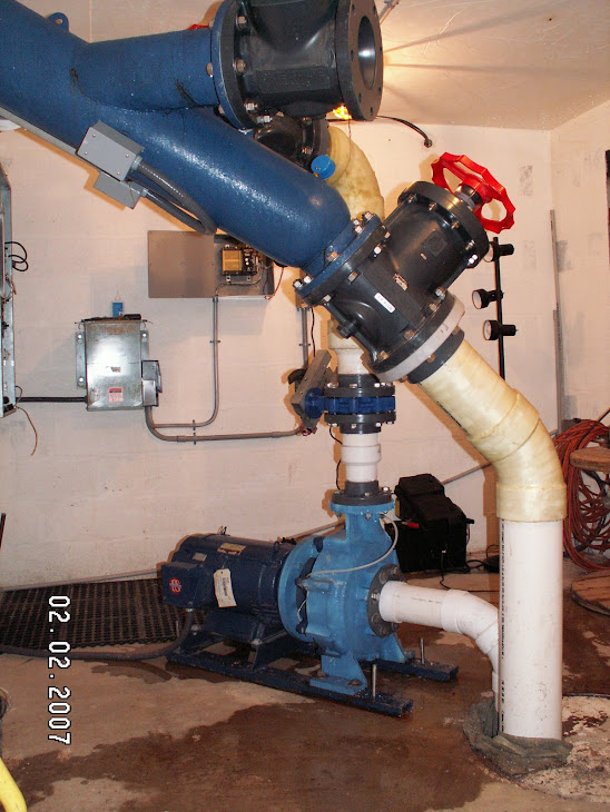
Below, the blown out schedule 40 T
static pressure 94 PSI, must have surged.


The fiberglass reinforced schedule 40 elbow.

Friday, July 23, 2010

Dealing with sand, gravel, ice, leaves just to mention a few things in the water.

PVC moving belt trash rack


Frazil ice, leaves and gravel have been my biggest maintenance headaches. But I'm hoping those headaches are behind me now that I've designed and built a PVC moving belt trash rack.

Freezing up of the intake screen after 3 to 4 nights of subzero temperatures is a common problem in cold climates. As the water splashes down over rocks it ends up supercooled (30°F) and slushy. The instant supercooled water hits any cold material, especially metal, it sticks and builds up, shutting off the largest of openings, even with trash rack / screens totally removed.

In a case here I have a 48" wide X 8" high opening at the inlet end of a 30 ft near horizontal covered flume that leads water to a 4' X4'X 5' deep box with a plastic, moving conveyor screen installed near the top that dumps debris and slush (sometimes referred to as frazile ice) over the downstream edge of the box. The penstock pipe leaves the bottom of the box and the whole thing is covered with PT 2X.

Now I thought I had my freezing intake screen problems solved, using a covered, PVC, moving screen, that runs mostly underwater except for the 6 inches or so that sticks out over the edge of the baffle to dump the leaves, gravel and ice. This screening arrangement allowed me to remove the metal trash rack at the 48"X8" entrance to the flume. ' Thought that big hole would never be able to freeze up with water running into it. Wrong!  The water gets so thick with slush that it dams up the stream itself, then naturally, the ice dam overflows and the overflow freezes on the lip of the ice dam. And so, once the slush freezes solid, you get these interesting ice stairs, ice dam with level ice behind it, then another ice dam with level area... and so on up stream. Usually after a few days of ice stair formation, and as daytime temps rise, the water and slush disappear from the surface and water will continue to run underneath the now frozen hard ice cover. So long as the ice cover remains it will keep the water from supercooling and forming slush. You will have no problem running your micro hydro as the water runs under the ice cover. But how to deal with those few days of slushy ice damming water?

A deep (6') collection reservoir will go a long way toward solving this problem, but my stream flows over bedrock before falling off a cliff. A small dam would probably work but for various reasons was ruled out for now. I thought about heating tapes. They might ease the slush formation in the immediate area of the intake. They would have to be put inside antifreeze filled iron pipes to protect them from the rocks, logs and other storm debris. But thinking along these lines I remembered that we have a spring on a somewhat distant higher hillside. I had previously run a 1 1/2" PVC pipe from this source of 50°F spring water to our house for use as a domestic water supply. There is plenty of water especially in winter.  So I ran another 500' of 1/2 inch PVC downhill to the 48X8 problem intake flume and squirted the warm? water out upstream from the flume. This did the trick, at least this last winter, which was plenty cold. I think this could also work with pumped well water which is also relatively warm. The water would only have to run for the few days before the ice covers the stream. The pipe would retain more heat if it were buried and/or insulated, it should be pitched so it drains out completely when shut off.


You can purchase plastic conveyor belt with a large % of open space for the water. Order it to size or get it used (cheap) on Ebay and reconfigure it to the size you need. I am anxious to try this stuff in really cold weather. I have had to remove my old metal screen whenever the temps went below Zero °F. I also covered the whole intake flume, box and screen to keep it from freezing up. So far it has worked very well to keep all kinds of debris out of my penstock. The excess water that does not go down the pipe rinses the leaves off as they invert over the drive roller. The 18 RPM Bodine gear motor is directly coupled to the 3" PVC pipe that drives the screen. A slew of 3/16 holes drilled into the PVC pipe in exact locations matching the screen holes, and fitted with plastic pins, gives positive traction to the screen. Even though the screen moves slowly at about 6"/second, I still put a timer on the drive motor so it is on for 3 minutes then off for 6. This saves energy and wear and tear.


The PVC belt is made up of small sections hinge pinned together with 3/16" plastic (welding) rod to make any size screen. The short section of belt wrapped around the PVC pipe allows the accurate drilling of holes to accept short (1/2") pieces of 3/16 rod that act as sprocket teeth. I had to make the outside diameter of the standard 3" PVC pipe bigger by 1/4 inch to get it to accept the pitch of the plastic belt. If you are going to build this send me an email and I'll send you more specific 'how to' info.


Here is how I got my belt, and I turned the square hole sprockets on the lathe to just fit inside the 3" PVC pipe so it could be driven with a square tube drive shaft.


The basic drawing of the whole thing. Double (or Right?) click on the image to see it enlarged.


The 'Gravel Baffle Box' with the covers removed from the butterfly valve drive (left) and the screen drive motor box on the right. (looking up stream, the dam and falls are behind the viewer)

Monday, July 19, 2010

Monday, February 15, 2010

Pumps as Turbines (PaT) Motors as Generators


I have been using Pumps as Turbines and motors as generators very successfully for almost four years now. The optimum (maximum power) speed of a PaT is around 1/2 of its no load speed. So to test,run your PaT and generator with the available head but no electrical load or excitation. Then, for maximum power, you should load the system so it runs at 1/2 this No Load speed. So let's assume you have a six pole electric motor running as a generator at 1200 RPM (nominally). You would be looking for a No Load speed of (approximately) 2400 RPM at the generator shaft. If the PaT is direct coupled the only thing that can be tuned is the impeller diameter assuming the head is fixed. Cut down (on a lathe) the impeller diameter to increase the No Load RPM. If the generator is coupled to the PaT by a V belt the shiv ratios can be changed to give the correct RPMs.


How can I estimate roughly the maximum no load speed when impeller diameter and the net head are known?


No Load RPM= (19.1)(SQRT(64 H))/D
Where H= Head in feet, D= impeller diameter in feet (not inches)

So if H = 200 feet and Impeller Diameter is 7 inches we get a No Load RPM = 3699
This is a little high for a 4 pole (1800 RPM) generator, I'd rather be on the low end for better efficiency (less friction due to lower velocities). I would choose an 8" impeller. Or, (even better) go to a 6 pole 1200 RPM (direct coupled) motor, bring the no load speed down to 2400 RPM and calculate the required impeller diameter as below.


More often, you would know the full load normal operating speed of the generator to produce 60Hz from the name plate or the number of poles. Also the head is fixed and known. So you'll want to know what the impeller diameter should be for a direct coupled setup:


Impeller Diameter in inches = 230(SQRT(64 H)/R


Where H = head in feet, R = No Load RPM and SQRT = Square root


So if H = 200' and R = 2400, we get an impeller diameter of 10.8 inches.


These admittedly rough calculations work well with Pelton wheels as well as Francis type runners.


By the way, larger pumps are well designed and optimized to be very efficient. When run in reverse as turbines they perform just like Francis type turbines and are every bit as efficient, assuming you match up head, impeller diameter and operating speed.
The graph above shows how I reverse engineered the pump curves for for operation as a turbine. This analytical approach is not as easy to understand as the empirical approach described above. Note the U shaped > 73 % efficiency region. This is where you want to be operating this particular PaT with a 12 inch impeller, 230 ft of head, and using 750 Gpm with expected output of 25 Hp mechanical energy. BTW, pumps are designated by their outlet X suction inlet X impeller diameter. So this is a 3X4X12 end suction pump with a 30HP, 1800 RPM 3 Phase electric motor.

Thursday, February 11, 2010

Rolling logs uphill unloading from a trailer.

In the early 90's I built a circular saw mill on the back 40. I pick up logs in the local area, often felled by homeowners, and I often end up with a trailer load of big heavy logs to unload at the mill. I put a winch in the back of my old F250 and here is how I load and unload my trailer by just pushing a button.


Best little Hydro House in NY, 20 KW of renewable energy.

A quick overview of the building process. Picked up some inspiration in Costa Rica where pelton wheels could be seen laying around in yards, as ornaments, like wagon wheels here in the US. This is my first attempt at creating a video with music composition. So keep in mind, I'm an engineer not a liberal artist.


It appears my video's no longer play since Google takeover.